


In today’s era of the Internet of Things (IoT), smart home automation has evolved from being a luxury to an accessible and essential part of modern living. This project demonstrates a scalable and real-time home automation system built around the powerful IndusBoard Coin, a compact development board based on the ESP32-S2 microcontroller.
The system allows users to wirelessly control multiple AC appliances like lights and fans through an interactive web interface hosted directly on the board itself, without requiring any external cloud services or mobile apps.
Unlike traditional automation systems that only offer ON/OFF control through relays, this project takes a step ahead by integrating PWM-based fan speed control, enabling smooth real-time adjustment of AC fan speed via a slider on the webpage.
The board generates PWM signals from its GPIO pins, which are then sent to an AC Fan Speed Controller module that modulates the fan speed accordingly.
At the same time, standard relay modules are used to control the switching of lights and fans. The Coin board’s GPIOs are connected to the relay modules, acting as electronic switches for turning appliances ON or OFF with a simple tap on the web interface.

The system runs on Wi-Fi Access Point (AP) mode by default, allowing users to connect their phones or laptops directly to the IndusBoard’s Wi-Fi (SSID: IndusBoard_AP) and access the control panel through a browser.
However, this can easily be modified to Station Mode (STA), where the board connects to your home Wi-Fi network. In this mode, any device on the same network can access and control the system through the board’s local IP address, enabling seamless integration into existing smart homes.
One of the major advantages of using the IndusBoard Coin is its high number of available GPIOs (30+ pins), which means this system is not limited to just two lights and a fan. It can be easily scaled to control additional appliances by simply connecting more relays or PWM controllers to unused GPIOs and expanding the user interface accordingly.

For example, additional buttons and sliders can be added to the webpage to control more lights, fans, or even future sensors like motion detectors, temperature sensors, or LDRs.

Bill of Material
| Components | Quantity | Description |
| IndusBoard Coin | 1 | IndusBoard Coin |
| Relay Module (5V) | 1 | Channel Relay Module (5V) 250V AC |
| Fan Speed Controller Module | 1 | Fan Speed Controller Module |
| 5V DC Adapter | 1 | 5V DC |
Circuit Diagram

Here, IndusBoard Coin acts as the central brain of the entire smart home automation system. It not only processes control commands but also establishes wireless communication by creating a Wi-Fi Access Point (AP mode) or by connecting to an existing Wi-Fi network using Station (STA) mode.
Through this connectivity, the Coin board hosts a real-time interactive webpage that allows users to control connected appliances directly from a browser. Using its multiple GPIO pins, the board sends digital control signals to various actuators such as relays and fan speed controller modules.
The relay modules, connected to GPIO pins (for example, GPIO 3 for Light 1 – GPIO 6 for Light 4), serve as the switching interface for AC appliances like bulbs or fans. These relays function as electrically operated switches, toggled by the digital HIGH or LOW outputs from the Coin board.
For fans, while a regular relay can only turn the fan ON or OFF, integrating a fan speed controller module, such as an AC dimmer or a PWM-compatible controller, enables variable speed control.
This module receives a PWM signal—typically from a pin like GPIO 21—where the duty cycle or firing angle of the signal determines the actual fan speed. This allows for a smooth and precise adjustment of fan speed directly through the web interface, providing a complete and advanced smart automation experience.
The relay module acts like an electronic switch that isolates and safely controls the AC side of the circuit. Each relay channel on the module has input control pins connected to one of the GPIO pins of the Coin board (for instance, GPIO 3 is connected to control Light 1, and GPIO 6 to control Light 2).
When a digital HIGH signal is sent from the Coin board to the relay input pin, it triggers the internal electromagnetic coil inside the relay, which closes (or opens) a switch on the AC side, allowing current to flow through the connected appliance.
To connect an AC bulb or other AC appliance, the Live (L) wire from the mains power supply is first connected to the Common (COM) terminal of the relay. The Normally Open (NO) terminal is then connected to one terminal of the AC bulb or appliance. The other terminal of the appliance is connected directly to the Neutral (N) wire of the mains supply.
When the relay is activated by the Coin board, the circuit between COM and NO closes, completing the path and powering ON the appliance. When the relay is deactivated, the circuit breaks, and the appliance turns OFF.
This configuration ensures that high-voltage appliances are safely switched using the low-voltage logic level control from the Coin board, keeping the user and the controller board isolated from dangerous AC voltages.
Multiple such relays can be connected to multiple GPIO pins on the IndusBoard Coin to control several appliances individually and in real time from the web interface.
Additionally, the system can be expanded easily due to the availability of over 30+ GPIO pins on the Coin board, making it highly scalable and adaptable for larger smart home setups.
Code
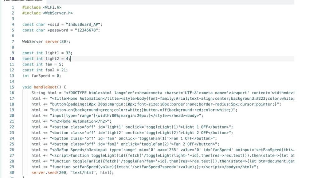
The code begins with the definition of GPIO pins assigned to control various appliances like lights and fans.
After that, a simple and interactive HTML webpage user interface (UI) is created within the code using embedded HTML and JavaScript, allowing users to control appliances in real time through any browser. The pinMode() function is used in the setup section to configure each GPIO pin as an output.
The Wi-Fi settings are configured to enable Access Point (AP) mode, so the IndusBoard Coin can create its own wireless network for users to connect directly.
The code also initializes the web server, defines routes to handle button clicks and fan speed control commands, and continuously checks for incoming client requests in the loop to ensure smooth operation of the automation system.
Testing
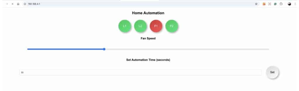
Now, power on the device and relay. Then, open the Wi-Fi settings on your phone or laptop and search for IndusBoard_AP. Connect to it using the password set in the code.
Next, open a web browser and enter 192.168.4.1 in the address bar. From there, you can control appliances such as light bulbs, fans, and AC units. Use the slider bar to adjust the speed and the text input to set automation. The system will automatically turn off all appliances after the specified time.
")


 continues to thrive")