


As we grow through our lives, we realise that we must take care of our previous and next generation members and it is a challenge to maintain their medication schedules in the middle of today’s fast-paced world, especially for elderly members, patients who are home-bound and children who are yet to develop their understanding. Adding more complexity to this is the fact, that some medicines need not be taken daily, but at an interval of 2-3-4 days. The Senior Pillbox aims to provide a low-cost, fully electronic circuit-based solution with minimal human intervention. We just need to ensure that we have refilled their daily dosage for the entire week and of course, an uninterrupted power supply!
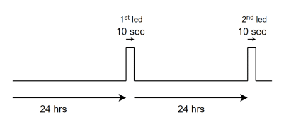
The system is meant to automate daily medication reminders with the help of both visual and audio alerts. It is noted that patients generally get irritated by noise intervention. To ensure that the Audio section (BT66/UM66 part, here) is not activated by erroneous signals, we have provided optical isolation using an opto-coupler IC. Every day, the reminder circuit lights up an LED (for 10 seconds in the present case) corresponding to the specific day of the week, and additionally, an audio indication is activated for a pre-decided duration (10 seconds, in the present case) for every gap of 24 hours. Once the alert is activated, the system goes back to calculate the next gap interval of the 24-hour cycle. For demonstration purposes, we have chosen 10 10-second (instead of 24-hour) interval and an alert duration of 1 sec (instead of 10 seconds) for ease of video recording.
The proposed setup is used as a combined LED and buzzer alert assembly. Figure 1 shows the author’s prototype of the entire setup. Figure 2 represents the block diagram of the Project.


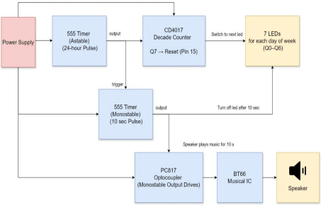
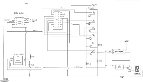
The Circuit is quite simple to operate. The first 555 timer (24 hr Astable mode) is connected to the clock pin of the CD4017 and also to the trigger pin of the second 555 timer. The second 555 timer (10s Monostable mode) has its output connected to the input of the optocoupler (PC817) and to the common cathode of the day LEDs. Each Q0 to Q6 output of the CD4017 is connected to a separate LED to represent the corresponding days of the week. The output of the optocoupler is connected to the trigger pin of the BT66 audio module. The BT66 output is fed to the base of a BC549 transistor, which drives the speaker connected between its emitter and ground supply. You can refer to figure 3 for an understanding of the timing diagram and figure 4 for the connections of the proposed circuit diagram. Table 1 is the bill of materials.
Bill of Materials
| Components | Count | Description |
| 555 Timer IC | 2 | For setting a 24-hour time in 555 IC |
| CD4017 Decade Counter | 1 | For 7-day LED sequencing |
| BT66 Audio Module | 1 | Plays an alert sound through the speaker |
| BC549 Transistor | 8 | 7 To switch LEDs ON/OFF & 1 for the speaker |
| Optocoupler (PC817) | 1 | To isolate BT66 from 555 IC |
| LEDs | 7 | One per day (Mon–Sun) |
| Resistor1 (26.6 MΩ) (AMV) | 1 | For setting a 24-hour time in 555 IC |
| Resistor2 (1 KΩ) (AMV) | 1 | For setting 24hr time in 555 IC |
| Resistor (1 MΩ) (MMV) | 1 | For setting 10sec time in 2nd 555 IC |
| Capacitor (4700 µf) (AMV) | 1 | For 555 timing (24 hr) |
| Capacitor (9/10 µf) (MMV) | 1 | For 555 timing (10s) |
| Speaker (8Ω) | 1 | For playing the sound |
| Breadboard | 2 | For prototyping the entire circuit |
| Jumper Wires | – | For all connections |
| Power Supply (5V) | 1 | Battery or DC Adapter |
| Diode | 1 | To prevent the opposite flow between the optocoupler pins |
Working
The main components of the device are two IC 555 timer ICs, a CD4017 decade counter coupled via an optocoupler IC to the BT66 audio module. The IC 555 timers form the system’s core, each configured for a distinct timing function. The first IC 555 timer operates in Astable mode and serves as the system’s main clock, generating a pulse once every 24 hours. This pulse advances the CD4017 counter to indicate the current day and triggers the second IC 555 timer. The second IC 555 timer is configured in Monostable mode and is responsible for generating a 10-second pulse. This pulse activates both the LED corresponding to the current day and the speaker, ensuring a combined visual and auditory reminder.
The values of the components are:
For (Astable 24 hr)
R1: 26.6 MΩ
R2: 1 KΩ
Capacitor:4700 µf
For (Monostable 10 sec)
Resistor: 1 MΩ
Capacitor: 9/10 µf
The CD4017 decade counter plays a crucial role in tracking the days of the week. It advances one output pin each time it receives a pulse from the astable timer, lighting up one of the seven LEDs labelled from Sunday to Saturday. Once it reaches the seventh output, the counter resets to the first output, thus creating a continuous weekly cycle.
The optocoupler acts as a safety and isolation component in the circuit. It allows the monostable timer to trigger the BT66 audio module without any direct electrical connection, enhancing reliability and preventing interference between the logic and audio sections. The BT66 audio module, when triggered, plays a preloaded sound for 10 seconds through a speaker, controlled via a BC549 transistor that acts as an electronic switch. Together, these components create a reliable and user-friendly system that ensures timely reminders for medication intake each day.
Connection among the main components:
| IC555A (24 hr) | IC555B (10 sec) | IC 4017 | BT66 | Speaker | PC817 | BC549 Speaker | |
| GND | Pin 1 Pin 5 via 0.01 µF Pin 2 & 6 via 4700µF | Pin 1 Pin 5 via 0.01 µF Pin 6 & 7 via 9µF | Pin 13 Pin 8 | Pin 1 | -(ive) end | Pin 2 via 470 Ω | – |
| +5V | Pin 4 Pin 8 Pin 7 via 26.6 MΩ 1 KΩ between Pin 6 & 7 | Pin 4 Pin 8 Pin 6 & 7 via 1MΩ | Pin 16 | – | – | Pin 4 | – |
| IC 555A o/p (Pin 3) | Pin 3 | Pin 2 | Pin 14 | – | – | – | – |
| IC 555 B o/p (Pin 3) | – | Pin 3 | – | – | – | Pin 1 | – |
| Not connected | – | – | Pin 9 Pin 11 Pin 12 | – | – | – | – |
| – | – | – | – | – | +(ive) end | – | Emitter |
| – | – | – | – | Pin 2 | – | Pin 3 | Collector |
| – | – | – | – | Pin 3 | – | – | Base |
IC 555A is for a 24-hour hour duration-Astable Mode of operation
IC 555B is for 10 10-second duration-Monostable Mode of operation
For Pins 1-7, 10 and 15 of IC CD4017, please check the table CD4017 mapping to weekday LEDs.


