


In modern electrical systems, safety is of utmost importance to prevent hazards like electric shocks, fires, and damage to equipment caused by earth leakage currents. Earth leakage protection devices play a crucial role by monitoring the current flow from a system’s conductors to the ground, providing an essential safeguard in the event of electrical faults. These devices detect small leakage currents, ensuring the protection of both users and equipment. This article explores how earth leakage protection devices work, their construction, and their various applications.
Circuit Working
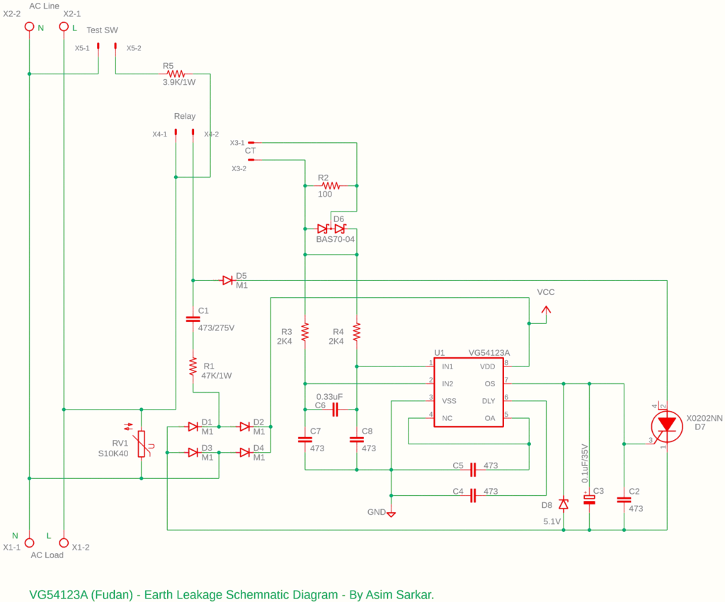
The VG54123A is a highly sensitive earth leakage protection device designed to detect leakage currents in electrical systems. The core working principle of this device involves monitoring the difference in current between the live (phase) and neutral conductors. Under normal conditions, the current entering the live conductor should be equal to the current leaving through the neutral conductor. In the schematic, a Current transformer (CT) of 500:1, CT output is connected to the X3 connector in the schematic. This is used to sense the leakage, ensure both the Line and Neutral is passed through the CT.
In case of an earth leakage, the current flow becomes unbalanced, causing a differential current to flow through the ground. The VG54123A senses this imbalance through the current transformer, triggering a protective action such as switching off the system or alerting the user to a potential fault. A ‘Relay’ can be used for a cut-off mechanism.

When the leakage current exceeds a predefined threshold (typically a few milliamps), the device immediately disconnects the power supply to prevent any harm or damage to the system or individuals.
There also a connection to the leakage test button marked as ‘Test SW’ in the schematic and another line of it is connected to the Anode of the SCR. This can be used to stimulate a fault condition similar to earth leakage.

Bill of Materials (BOM)
Here’s a typical Bill of Materials (BOM) for the VG54123A-based earth leakage protection circuit:
| BILL OF MATERIALS | |
| Components | Quantity |
| VG54123A – Earth Leakage IC (U1) | 1 |
| 0.1uF/35V – E-Capacitor (C3) | 1 |
| 0.33uF Capacitor C0805 (C6) | 1 |
| 100 Ohms Resistor R0805 (R2) | 1 |
| 2K4 Ohms Resistor R0805 (R3, R4) | 2 |
| 3K9 Ohms 1W Resistor (R5) | 1 |
| 47nF Capacitor C0805 (C2, C4, C5, C7, C8) | 5 |
| 47nF/ 275V Capacitor (C1) | 1 |
| 47K Ohms 1W Resistor (R1) | 1 |
| 1N4728 Zener Diode 5.1V DO41Z10 (D8) | 1 |
| BAS70-04 Silicon Schottky Diodes SOT23 (D6) | 1 |
| M1 Diode DO-214AC (D1, D2, D3, D4, D5) | 5 |
| X0202NN Thyristor 600V, 0.8A SOT223 SOT223 (D7) | 1 |
| S10K40 VARISTOR 40VAC (RV1) | 1 |
| Current X’mer Ratio 500:1 (CT) | 1 |
| Relay DPDT 230VAC contact Panel Mount type (Relay) | 1 |
| Push Button 230AC (Test SW) | 1 |

Construction and Testing
Construction:
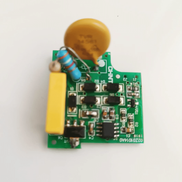
- Prepare the PCB: Start by designing (or build in a General Purpose PCB) that accommodates the VG54123A IC, current transformer, resistors, capacitors, and relay components. Ensure that the design is compact and the traces are correctly rated for current handling.
- Assemble Components: Solder the VG54123A IC onto the PCB. Follow with the placement of the current transformer for leakage current detection. Connect resistors and capacitors for circuit stabilization and protection.
- Relay and Power Supply: Mount the relay or connect an external relay, ensuring it is rated for the voltage and current of your system. The relay should disconnect the power supply when earth leakage is detected. Attach the power supply unit to provide the necessary voltage for the circuit operation.
- Enclosure: Secure the completed PCB inside a protective enclosure to ensure the safety of the device and users.
Testing:
To test the system:
- Leakage Simulation: Create a small leakage path (e.g., by connecting a high-resistance path between the live conductor and ground) to simulate earth leakage. Test Switch is provided in the Schematic to generate leakage current through the system via 3.9K Ohms resistor
- Monitor Relay Action: Observe the relay’s response when the leakage current exceeds the threshold. The relay should trigger and disconnect the power.
- Repeatability: Perform multiple tests with varying leakage current levels to ensure the device is consistent in its performance.
How Earth Leakage Protection Works
Earth leakage protection devices primarily protect users and systems in the following ways:
- Preventing Electric Shocks: If leakage current passes through a human body, it can cause severe or fatal electric shocks. The device quickly detects this and disconnects the power supply before harm occurs.
- Preventing Equipment Damage: Even small leakage currents can lead to malfunctioning or permanent damage to electrical equipment. The protection device ensures these currents are detected early, minimizing the risk of costly repairs.
- Reducing Fire Risks: Earth leakage currents can cause overheating, which may lead to fires. By detecting and acting on leakage currents, the protection device helps prevent such fire hazards.
Various Applications
Earth leakage protection devices are essential in various applications, including:
- Residential and Commercial Buildings: Protect against accidental leakage currents from household appliances, lighting fixtures, and other electrical devices.
- Industrial Machinery: Safeguard sensitive equipment and workers in industrial environments from leakage currents.
- Medical Equipment: Ensure the safety of patients and healthcare personnel by monitoring leakage currents in medical devices.
- Outdoor Electrical Installations: Provide protection for outdoor electrical setups, such as street lighting and landscaping lighting, where moisture and environmental factors can increase leakage risks.
- Solar Power Systems: Protect renewable energy systems, particularly solar installations, ensuring safe operation and longevity.
Conclusion
Earth leakage protection devices are crucial for ensuring electrical safety. They protect users from electric shocks, prevent damage to equipment, and reduce the risk of fire hazards. Incorporating these devices into electrical systems helps ensure compliance with safety standards and reliable performance in various settings.


